Pigging valve is a new type of pigging device mainly used in oil, natural gas, chemicals and other liquid transportation pipelines.It has been widely used in oil and gas field, chemical industry, wharf, oil and gas storage and offshore platform.
Structural characteristics of
Pigging valves are of three types to suit different operating requirements.
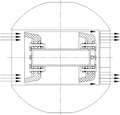
1、Type I pigging device:
Type I is a standard pigging valve for pipe cleaning.The device is slightly larger than the inner diameter of the pipe, which plays the function of transmitting and receiving the pig and also has the function of cutting off.
2、Type II pigging device:
Type II is a pigging valve with bypass, the device is slightly larger than the inner diameter of the pipe, in the hollow sphere perpendicular to the direction of the ball hole to open two circular channels, this structure to ensure that even in the launch or receive pig pigging pigging valve will not break flow, type II pigging valve can not be used as a cut-off valve.
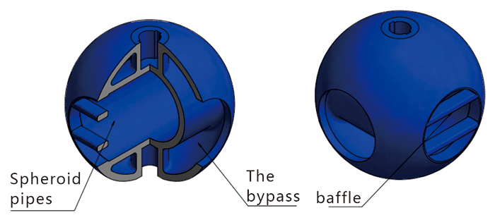
3、Type III pigging device:
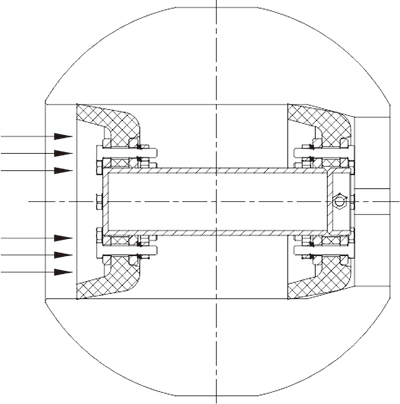
Type III is mainly for isolation and sequential delivery of medium to prevent medium mixing pigging valve.The device is slightly larger than the inner diameter of the pipe and has an additional seal in the ball hole of the receiving pigging valve to ensure that a seal is formed when the isolating pig reaches the receiving pigging valve.
The working principle of
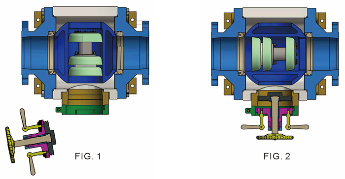
The sealing principle of the device is the same as that of the ball valve. Under the joint action of spring and medium, the valve seats on both sides are close to the ball, and the sealing channel is separated from the middle cavity of the valve body.The pigging is loaded, transmitted, received and taken out by rotating the sphere.When the sphere channel is facing the fast-opening blind plate, the pig can be loaded and taken out (see figure 1);After the ball rotates 90 degrees, when the channel of the ball is consistent with the pipe, the pig can be transmitted and received under the action of the medium (see figure 2).
Structure of pigging device
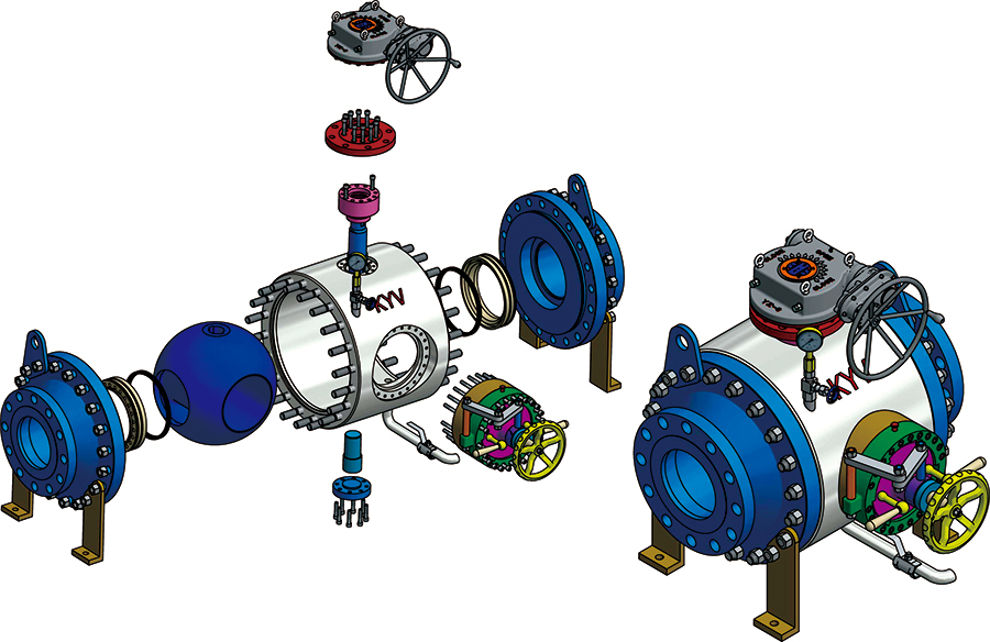
DN50--DN300(2"-12")
The operation process
1. Operate the worm gear to make the ball face the blind plate and observe the indication on the worm gear;
2. Open the pressure relief valve and observe the pressure gauge until the pressure is zero;
3. Rotate counterclockwise to bring the blind plate handwheel to the position of red line;
4. Pull out the locating pin;
5. Hold the blind plate handle with both hands and rotate anticlockwise until the mouth can be pulled out;
6. Pull out the blind plate and load it into the pig;
7. Check whether the o-ring is intact, push the blind plate, hold the handle with both hands and rotate along the needle to the blocking position;
8. Turn the blind plate handwheel clockwise to the closing position;
9. Plug in the locating pin;
10. Close the pressure relief valve;
11. Operate the worm gear to make the ball port consistent with the pipeline, and transmit or receive the pig

Structure of three - lobe clamp pigging device
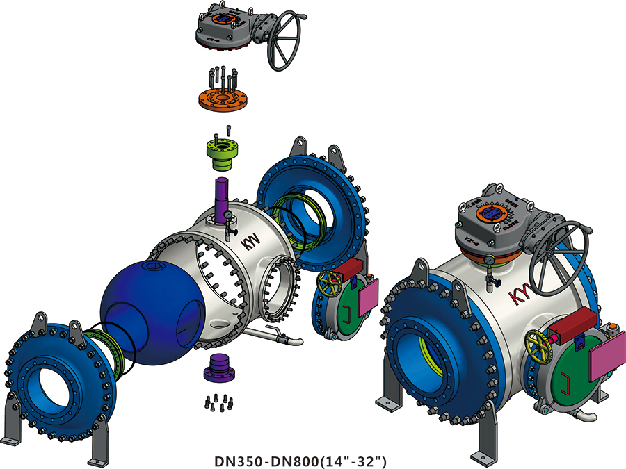
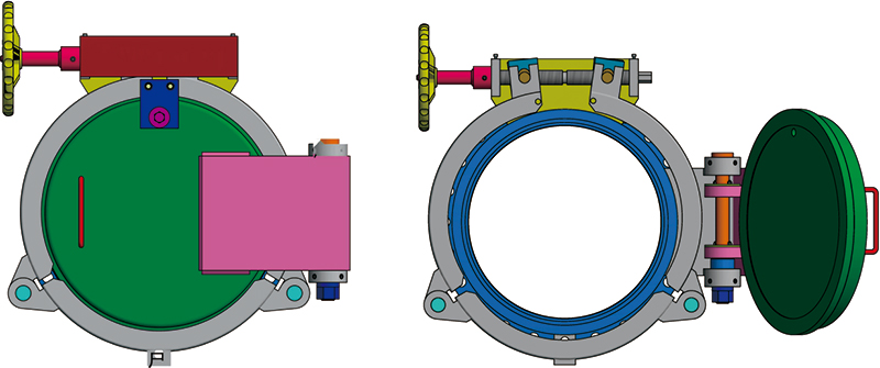
Three-valve quick opening clamp blind plate operation procedure
1. Operate the worm gear to make the ball face the blind plate and observe the indication on the worm gear;
2. Open the pressure relief valve at the bottom of the valve body and observe the pressure gauge until the pressure is zero.
3. Slowly unscrew the secondary pressure relief valve, stop the unscrewing when there is medium overflow, completely open the pressure relief valve when there is no medium overflow in the equipment, and remove the safety platen.
4. Rotate the lead screw counterclockwise until the inner edge of the clamp is completely separated from the outer edge of the blind plate cover, then open the blind plate cover.
5. Load the pig, check whether the o-ring is intact and close the blind plate;
6. Turn the lead screw clockwise to tighten the clamp;
7. Install the safety card board so that the safety card board is completely stuck on the cylinder pin;
8. Check whether the o-ring of the vent valve is intact, install the upper vent valve and tighten it;
9. Close the pressure relief valve;
10. Operate the worm gear to make the ball port consistent with the pipeline, and transmit or receive the pig;
Installation and use
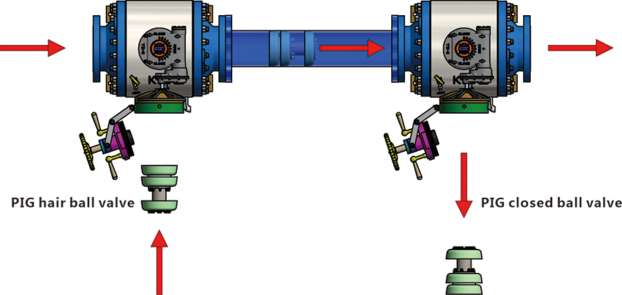
1. Pigging valves are usually used in a complete set, one for transmitting and one for receiving. Please note that the operating surface of blind plate should be on the left or right side of the flow direction when installation position is limited.
2. If there is a bend in the pipeline, a large bend should be used, and the bend radius should be at least 1.5 times DN; otherwise, the pig will get stuck when passing through.
3. The diameter of the matching valve shall not be less than the inner diameter of the pipe, so as to keep the channel smooth and avoid the situation that the switch is not in place, or the pig will be blocked or damaged.
Pick and serve skid mounting structure
The equipment consists of 1 pigging valve, 3 ball valves, 3 pressure gauge stop valves, pressure gauges, ball indicator, etc.The priming design not only meets the requirements of site use, but also has the characteristics of small footprint, energy saving, easy to move and strong applicability.When pigging valve in pigging device is maintained, the ball valve at the inlet and outlet of pigging valve of main line can be closed, and the ball valve of bypass pipeline can be opened to maintain pigging valve, without affecting production by closing production pipeline.
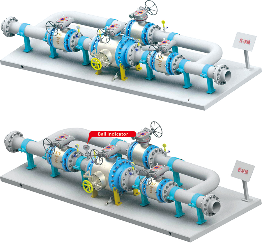
Schematic diagram of receiving and servicing skid pipe installation
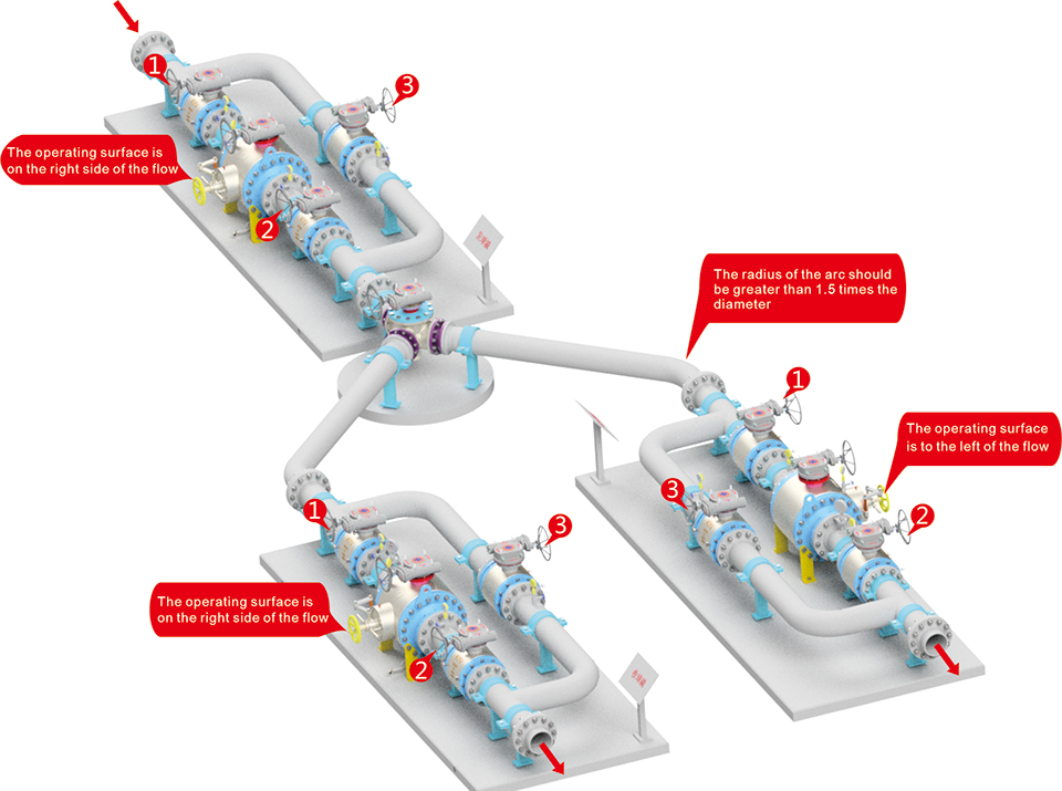
Remark:
1. After the pig is loaded, the ball valve 1, 2 is opened, and 3 is closed. The pigging valve is sent through the distributor to enter the ball collecting pry 1, and the distributor turns the Angle to enter the ball collecting pry 2;
2, ball valve 1,2 close, 3 open, medium from the bypass into the pipeline, can carry out pigging valve maintenance and maintenance;
3. The diameter of all matching valves in the pipeline shall not be less than the inner diameter of the pipeline to ensure smooth passage of the pig and no blockage;
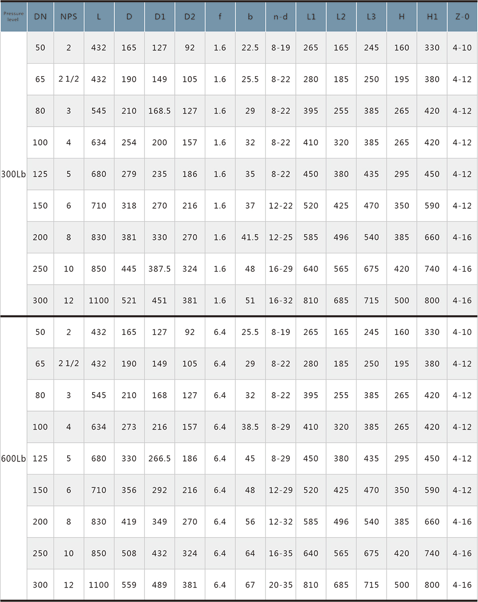
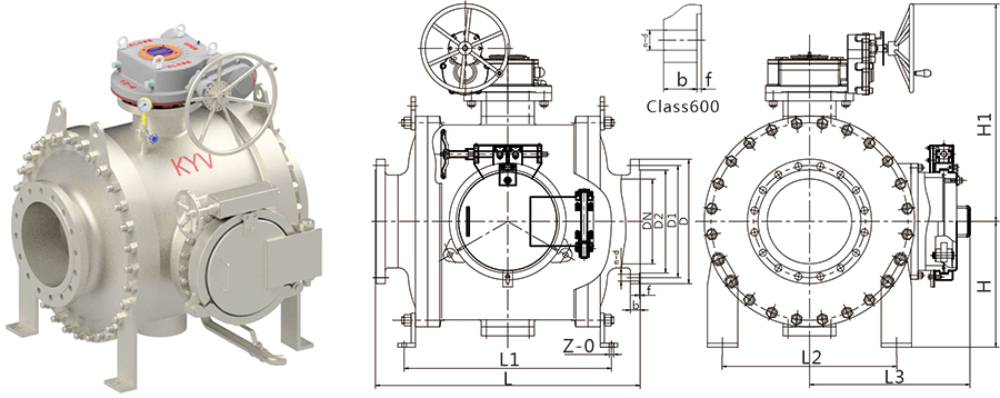
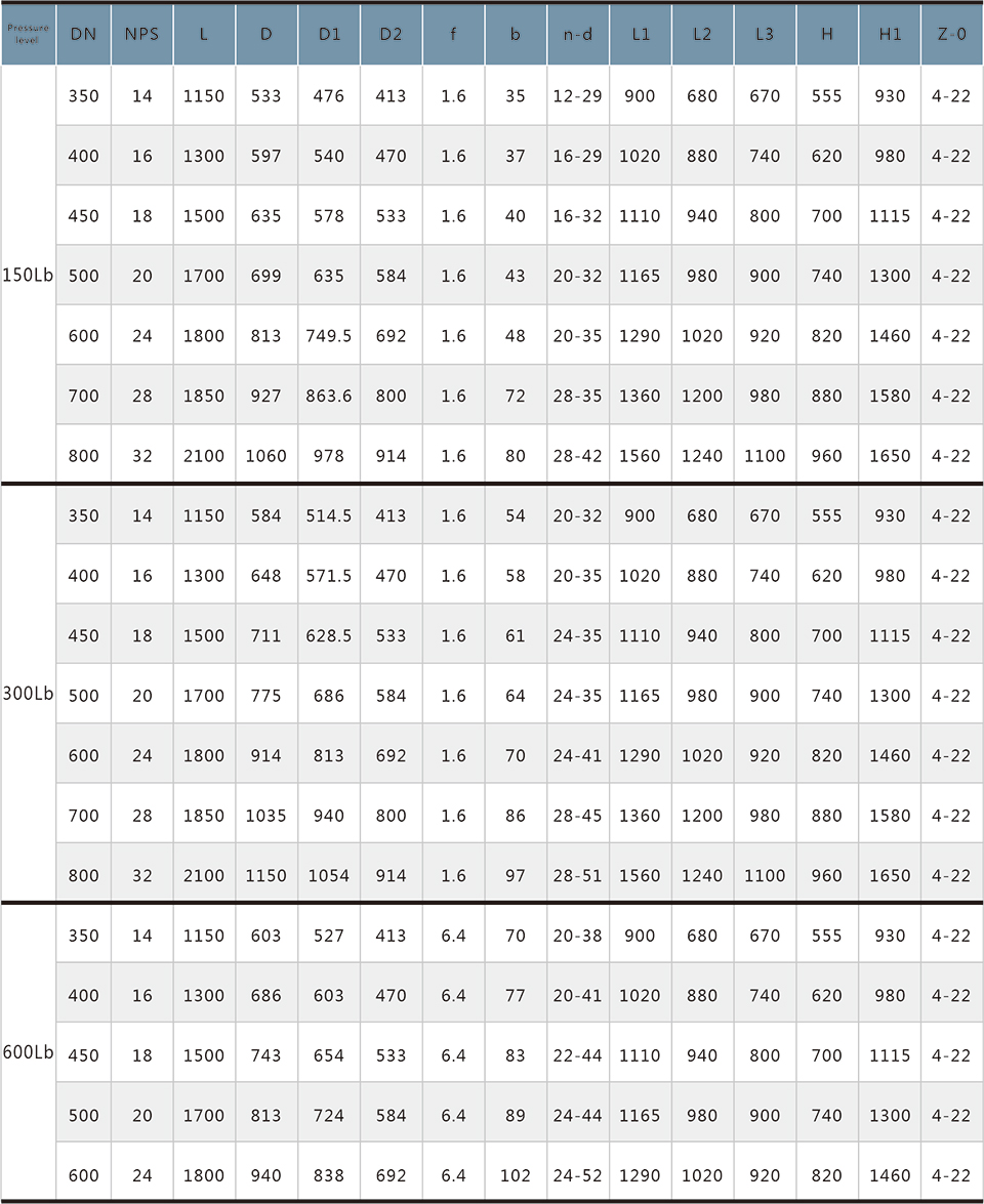
Shape and connection dimensions
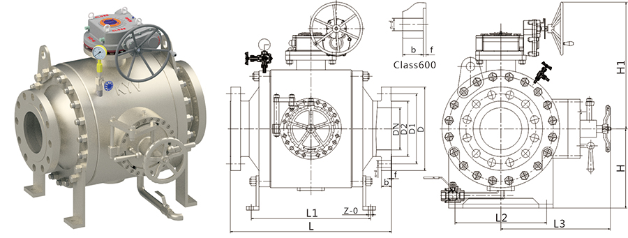
API ANSI B16.5-RF
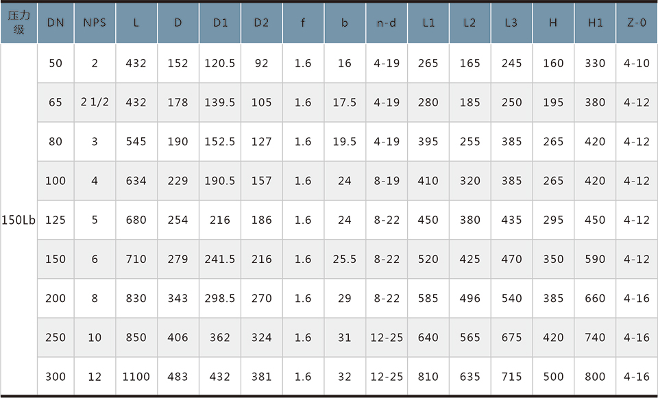
API ANSI B16.5-RF


Scan QR Code
learn more information